The electric motor is a transducer between the mechanical and electrical domain, which is based on energy exchange. This means that we have to model it with at least a transformer or a gyrator, and possibly parasitic effects. In this document, you find a description of how an electric motor internally operates – for the purpose of modelling.
The core functioning of an electric motor is based on the so-called Lorentz force. This force acts on a current that flows through a magnetic field as shown in Fig. 1.

Fig. 1: An illustration on the Lorentz force. Visible are two parts of a magnet, a north (N) pole and a South (S) pole. The magnetic field flows from the North to the South pole. A conductor is placed in the magnetic field that carries a current, I. The force F is the force that acts on the conductor as a result of the current I and the magnetic field B
The Lorentz force,  , is equal to:
 (Eq. 1)
Where:
 is the charge that is in the magnetic field
 is the velocity of the charge in the magnetic field
 is the magnetic field
 denotes the cross-product
 is a measure for current, as current is defined as the net rate of flow of electric charge () per unit of time (
 ):
):
 (Eq. 2)
We know that velocity  is distance per second:
 (Eq. 3)
Substituting Eq. 2 and Eq. 3 in Eq. 1, we obtain:
 (Eq. 4)
We can see that the magnitude of the force is dependent on:
- The magnitude of the current,

- The length of the wire that is in the magnetic field,

- The strength of the magnetic field,
To increase the force that can be delivered, the current conducting wire is wound into a coil to create a lot of length of the wire that is in the magnetic field. This coil (often with an iron magnetic core to guide the magnetic field) is then mounted on a shaft. The total is called the rotor as shown Fig 2.

Fig. 2: The rotor of an electric motor
The rotor is suspended in (ball) bearings in the magnetic field.
As we can see in Fig. 1, the force is always perpendicular to the direction of the current and the direction of the magnetic field. As the coil is mounted on a shaft, the Force is converted to a Torque ( ) through the (average) moment arm
  :
:
 (Eq. 5)
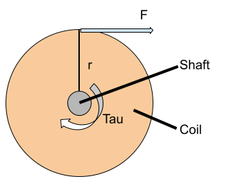
Fig. 3: A force on the coil is converted in a torque around the shaft.
Combining Eq. 5 and Eq. 4, we obtain:
 (Eq. 6)
We can simplify Eq. 6 to:
 (Eq. 7)
Where  is the motor constant, which is determined by properties of the electric motor, such as the field strength , the average radius and the length of the wire .
Based on the physics of the Lorentz force, we know the relation between the torque and the current. The core (ideal) behaviour of an electric motor is power continuous, based on this property, we can determine the relation between the rotational velocity,  , and the voltage, :
 (Eq. 8)